Fusors: internal electrostatic containment
Fusors use electrostatic potential to confine plasma in order to accomplish nuclear fusion and are currently used for neutron production (a by-product of Deuterium-Tritium or Deuterium-Deuterium fusion) for the production of certain radioactive isotopes such as Mo-99. Net power generation remains out of reach for the fusor or related designs (see Bussard’s polywell), as is currently the case for all fusion devices.
Fusor under high power
THe first fusor was the Farnsworth-Hirsch design that directed ion beams (or electron beams) at a central location in an evacuated chamber to create a stable area of plasma with high electrical potential. This is a demo model of a Hirsch-Meeks fusor, which instead uses two charged grids to form an electrostatic potential well inside the inner grid. This model here was built only to display the plasma containment of the inner grid and does not fuse nuclei to any significant extent.
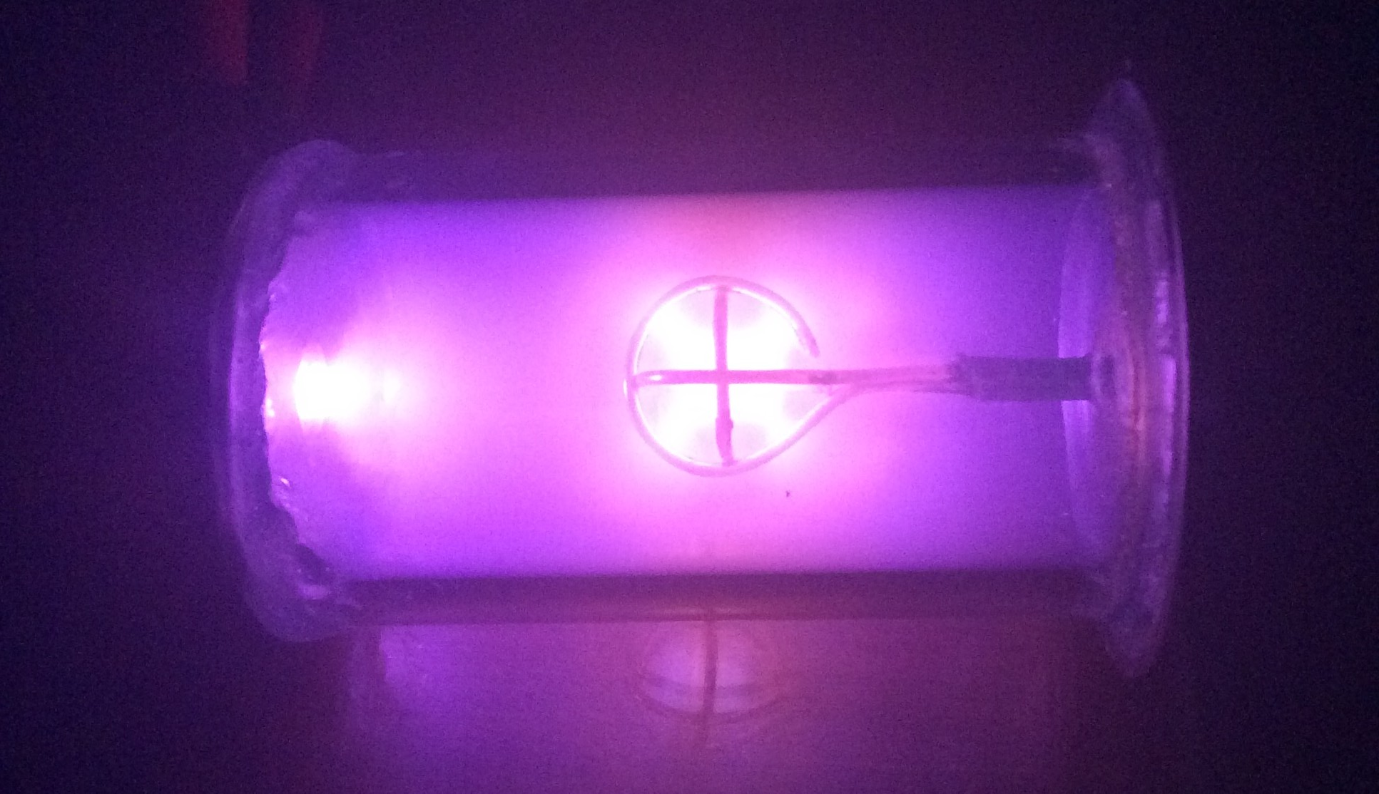
The small vacuum chamber self-rectifies, and the fusor is running here on a 14 kV @ 70mA AC input.
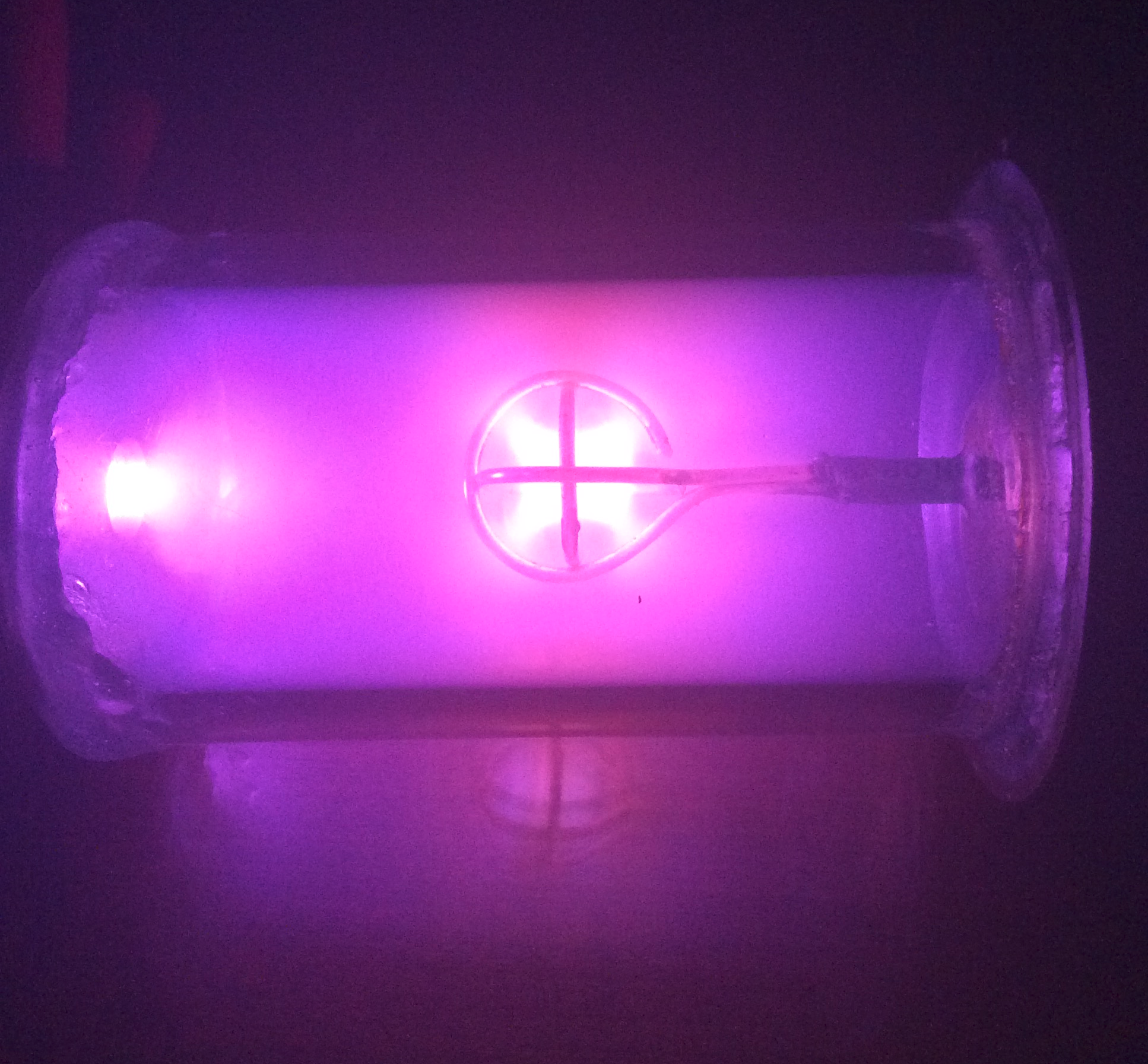
The whole device heats up rapidly under full power, and moreover the plasma burns the inner face of the borosilicate glass over time. The inner grid becomes especially hot, and on longer runs was capable of melting the 2 part epoxy used to seal the chamber.
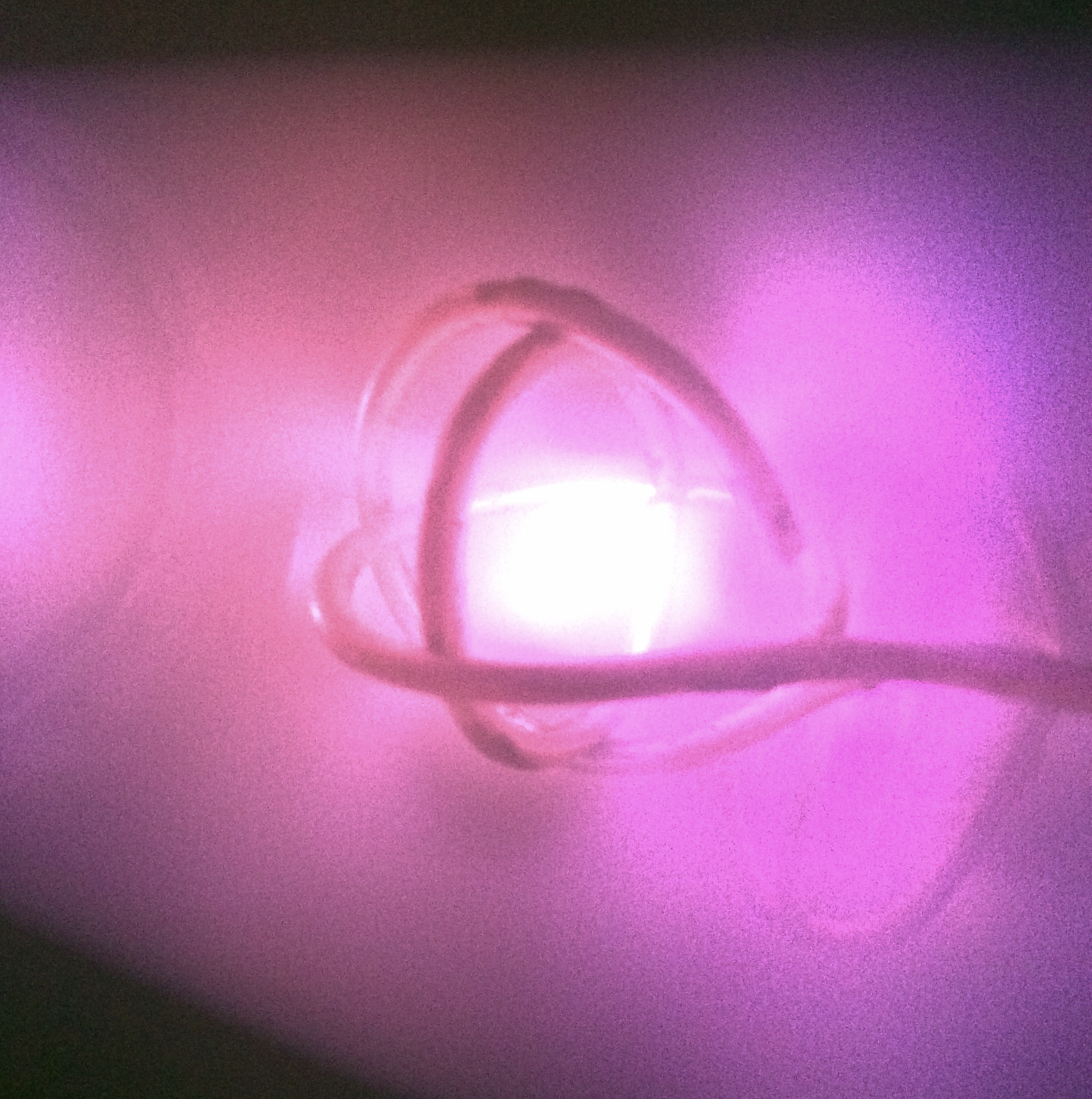
Fusor under low power (~400 V AC)
At a vacuum estimated at 50 microns, this fusor design ignites plasma at under 400 volts of AC input.
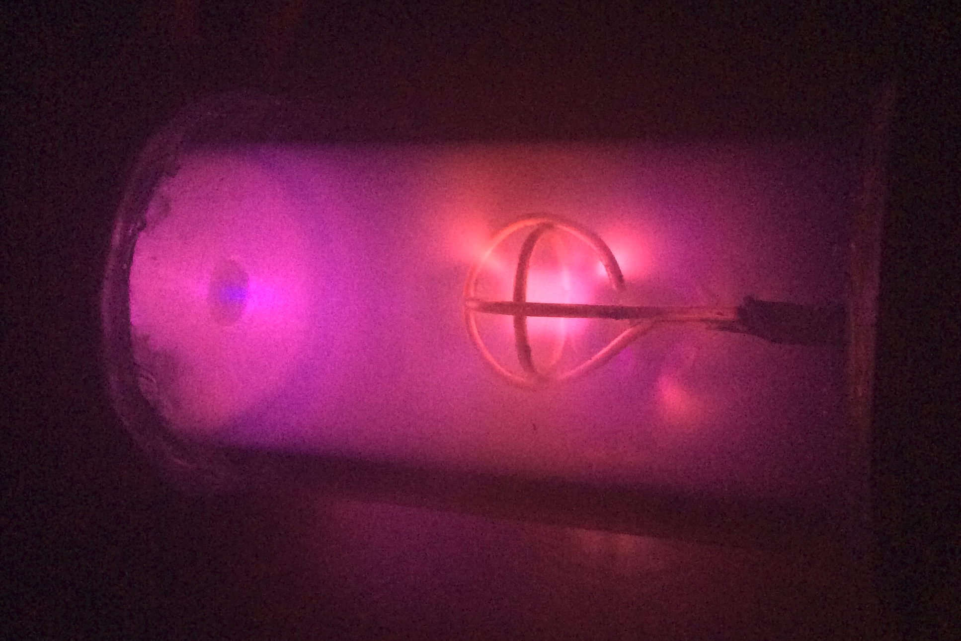
Note the dark regions around the inner grid, also visible in the high power images above. These are regions of high potential. THe electron distribution function is
\[f(u) = Ae^{\frac{-((1/2)mu^2+q\phi)}{KT_e}}\]where $q\phi$ is the potential energy, $KT_e$ is the thermal energy of the particles, $(1/2)mu^2$ is the electron’s kinetic energy, and $A$ is the constant
\[A = n \left(\frac{m}{2\pi KT} \right)^{1/2}\]$n$ is the plasma density, $K$ is Boltzmann’s constant, and $m$ is the mass of the particle (in this case an electron).
Note what this implies: as potential increases, the number of electrons decreases. The areas of highest potential are adjacent to the grid, which is an (albeit very idealized) explanation for why the plasma at least partially avoids the grid itself.
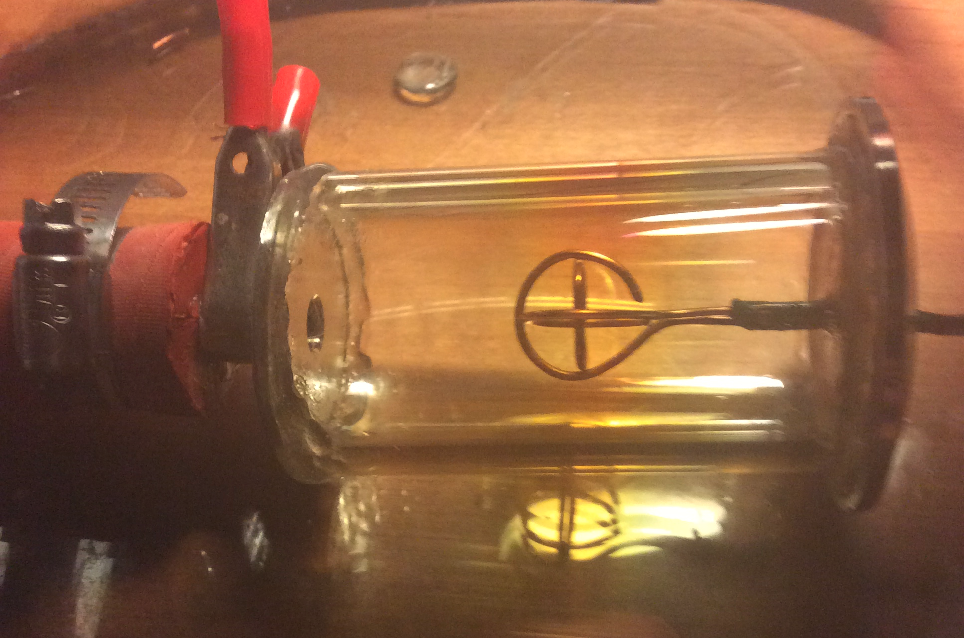
Fusor vacuum chamber, power off
Fusor contain plasma with an electrostatic grid pair. Here, the outer ‘grid’ is the steel vacuum coupling visible on the left and the inner grid is made of solid copper, visible front and center. The chamber is approximately 7 inches in length and uses thick borosilicate glass (to prevent implosion from the pressure difference accross the chamber), and stainless steel couplings designed for use in high vacuum are attached via two-part epoxy to the ends of the borosilicate chamber. The red tube on the left travels to the vacuum pump. I experimented with a surplus high vacuum single stage pump (rated at 5 microns) as well as a standard HVAC single stage pump rated at 40 microns. The latter was used for most of the ignitions that are imaged here.
Note that one should only use glass that will not shatter if exposed to a temperature gradient for any kind of fusor! Borosilicate comes under various brand names and is far more resistance to temperature gradient-induced damage than standard silica glass.
Borosilicate is relatively transparent to UV ratiation, and as a fusor running a the above voltages can put out quite a lot of this it is necessary to add shielding that is opaque to UV. Most clear plastics fulfill this requirement, although it is important to check the material used to be sure. I used a polycarbonate shield which doubled as a safety barrier to mitigate any effects of chamber implosion. The chamber never did fail, but one does not want flying shards of glass going everywhere. Also keep in mind that x-ray radiation becomes an issue for higher potentials, as borosilicate is quite transparent to that as well.