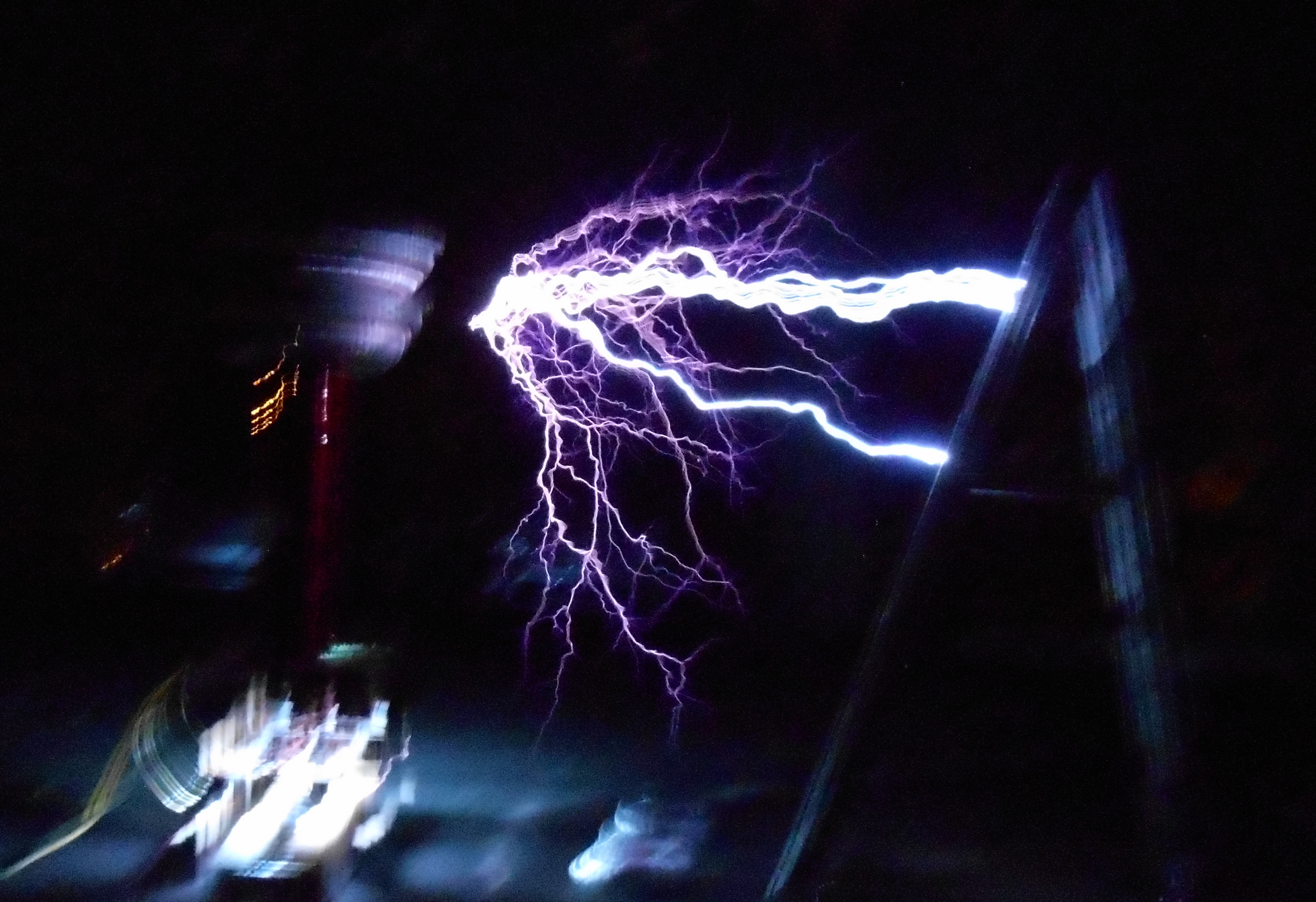
Tesla Coils: high voltage resonant transformers
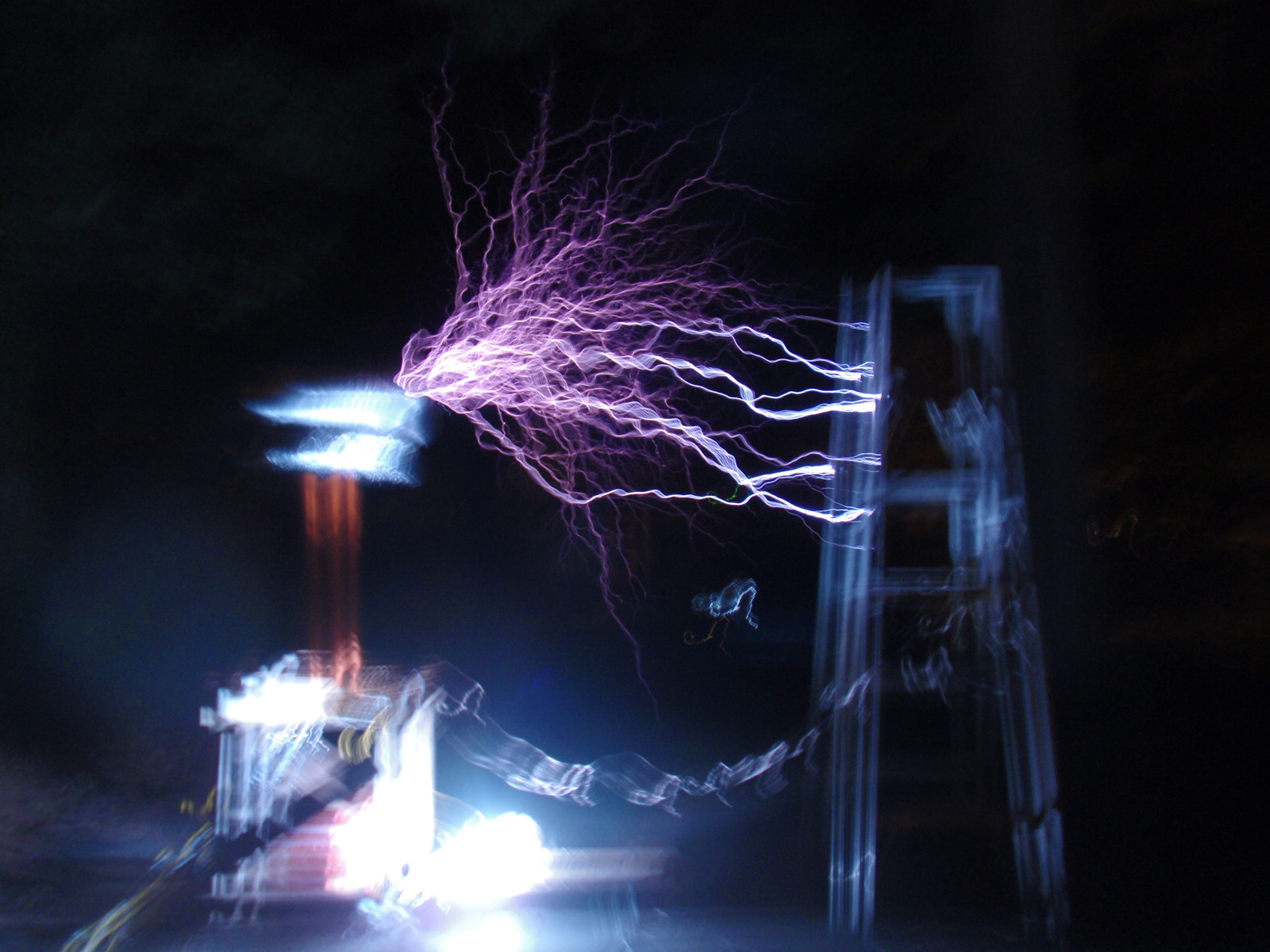
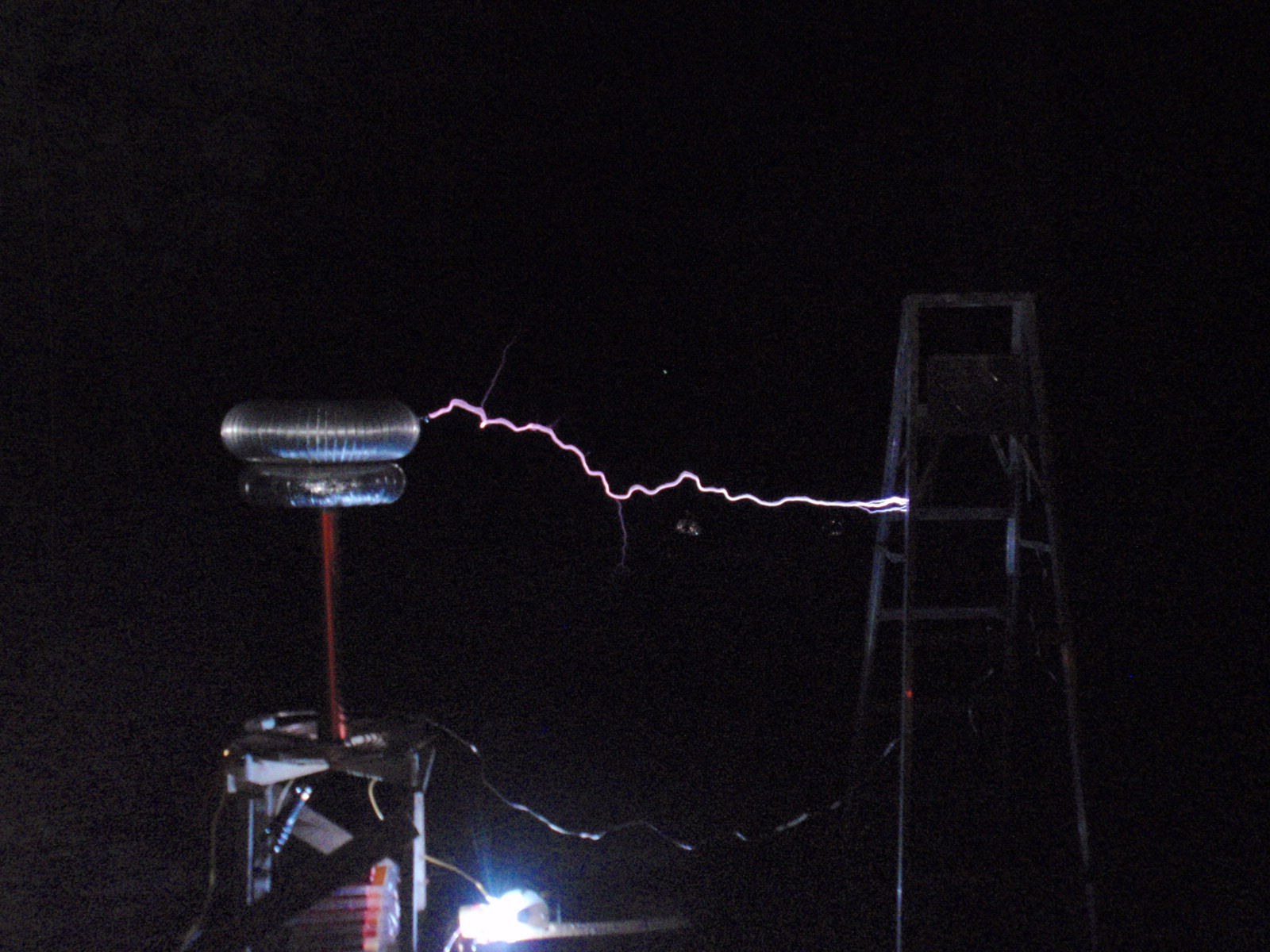
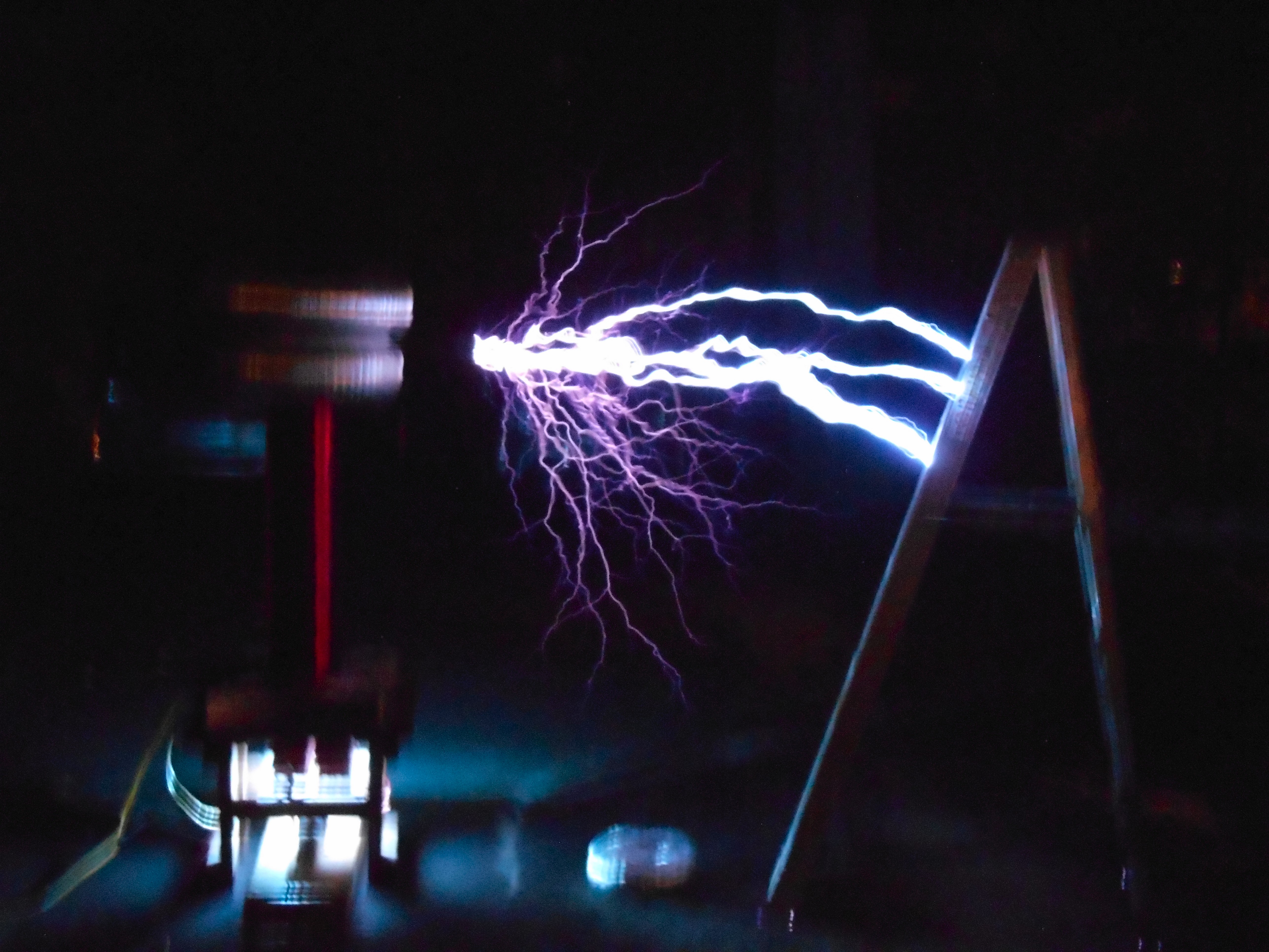
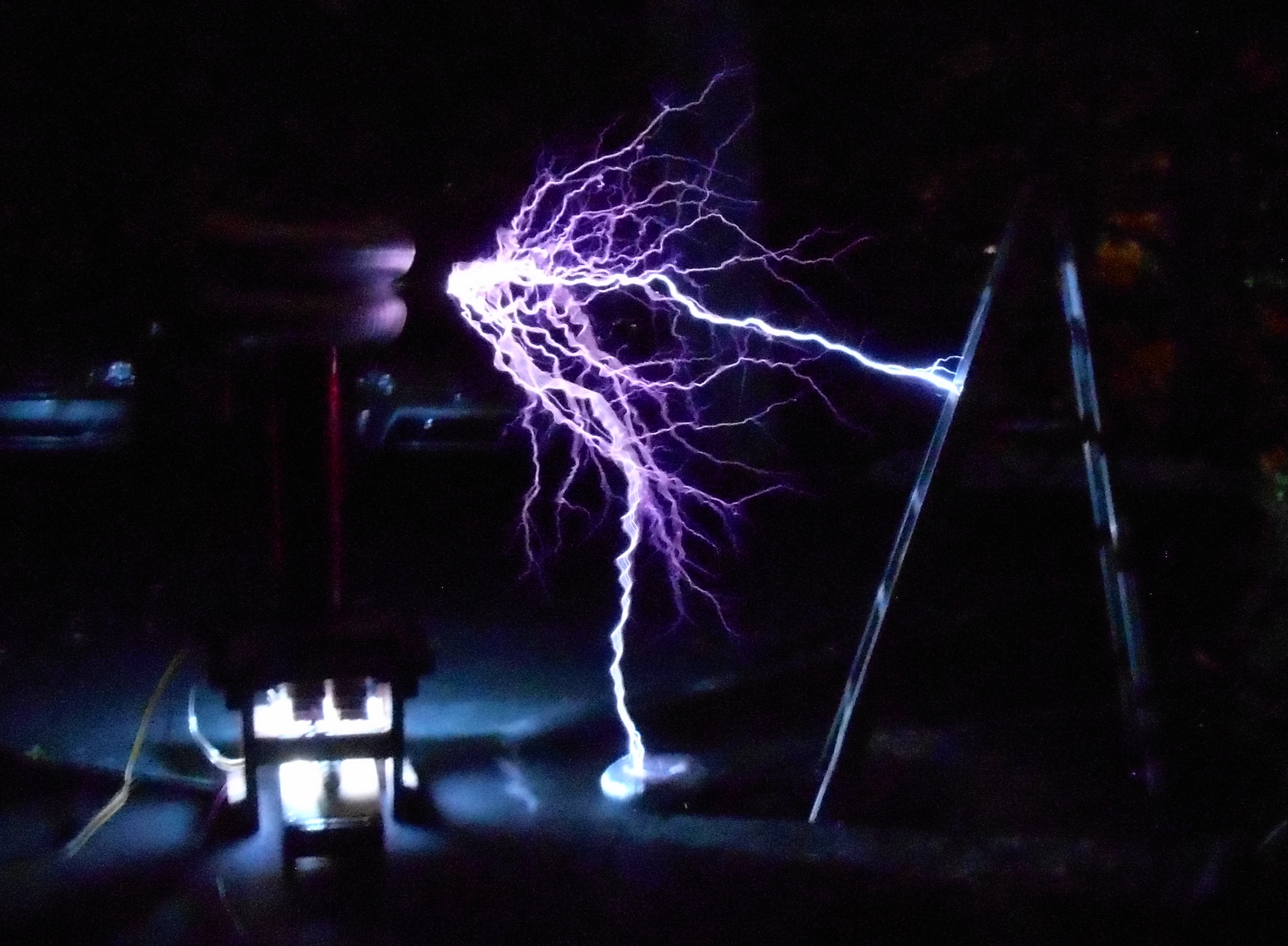
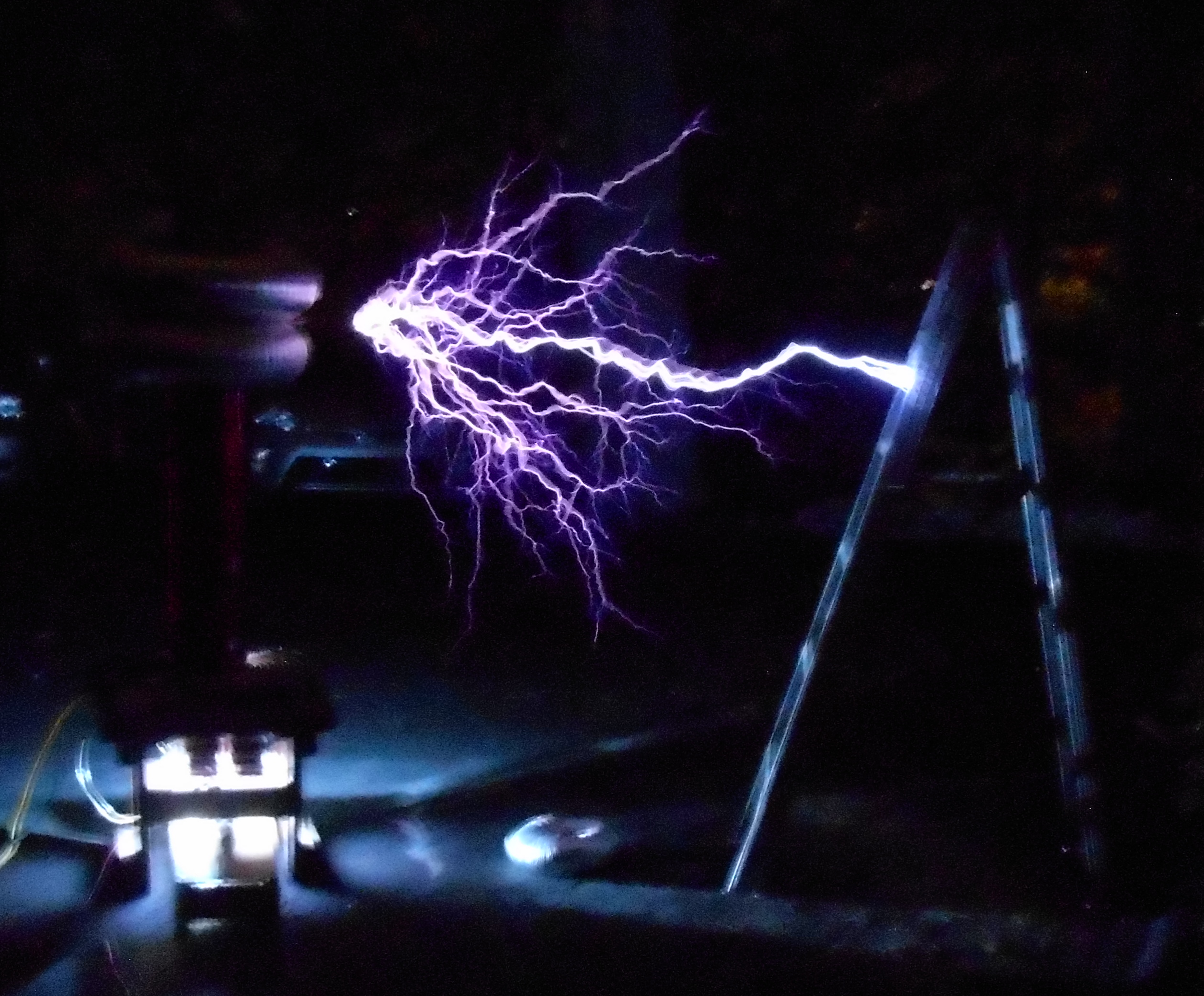
High voltage arcs. Beautiful to witness!
Specs: ~4 kVA power input using an ASRG spark gap running at ~500 bps, made from a variable-speed angle grinder with a disk (fashioned from high density polyethylene cutting board) securing four flying electrodes. The electrodes are brass as iron has high RF losses and get too hot to use with polyethylene, which is a thermoplastic and melts at high temperatures.
Tesla coils are air-cored resonant transformers, and are a type of LC circuit. The L stands for inductor, and C for capacitor and when combined with a device that allows for rapid capacitor charging (charged from a circuit power supply) and discharging (the spark gap), the LC circuit is capable of enormous changes in electromagnetic field strength over very short periods of time as it oscillates.
This rapid oscillation of thousands of volts means that most capacitors are unsuitable for the LC circuit. Here the primary circuit uses a 120nF multi-mini style capacitor made from a few hundred surplus WIMA FKP1 pulse capacitors usually found in industrial lasers. These are manufactured specifically to maintain good capacitance and not degrade while being sugject to rapid changes in voltage and current. Cheaper alternatives are glass bottles wrapped in aluminum foil, although these do degrade and do not have nearly the efficiency of industrial capacitors like the WIMA.
The LC circuit is powered by 4 microwave oven transformers, primaries wired in parallel with secondaries in series (floating cores, and all submerged in mineral oil) for a power ouput of 10 kV at ~400mA. Not pretty but a very inexpensive and robust power source. In fact, one of the only components I have used that has not failed catastrophically at one point or another: even when a primary strike led to a vaporized grounding wire (connecting the secondary to the iron core) in one of the transformers, repairs were minimal.
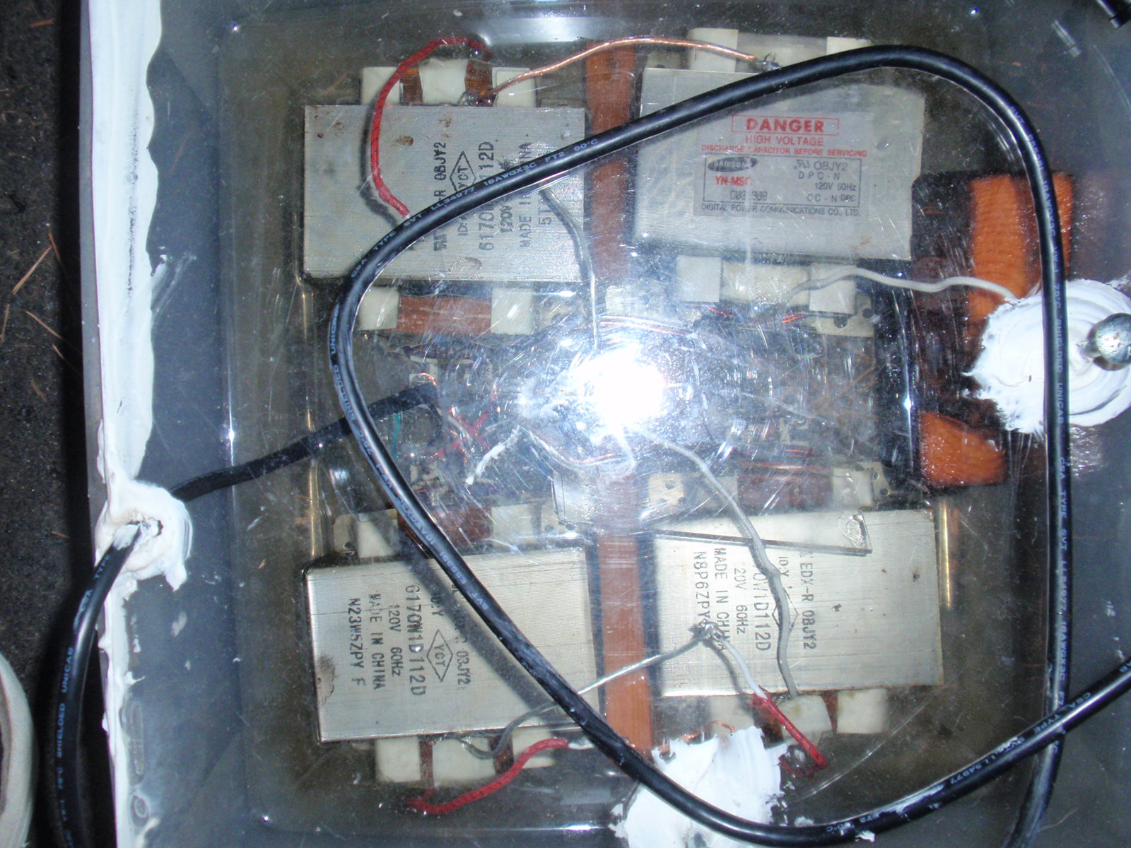
One point of caution: the oil used here is plain mineral oil from the grocery store. In terms of flashover and arc resistance, industrial transformer oil is far superior. But new transformer oil is quite expensive, and old oil can be hazardous. Be extra careful with any oil that has come out of a transformer, as it may contain polychlorinated biphenyls, aka PCBs, which are very toxic. PCBs were routinely added to transformer oil before the 1970s, and any used transformer or oil purchased and suspected to originate in this era should be checked to be free of PCBs before use.
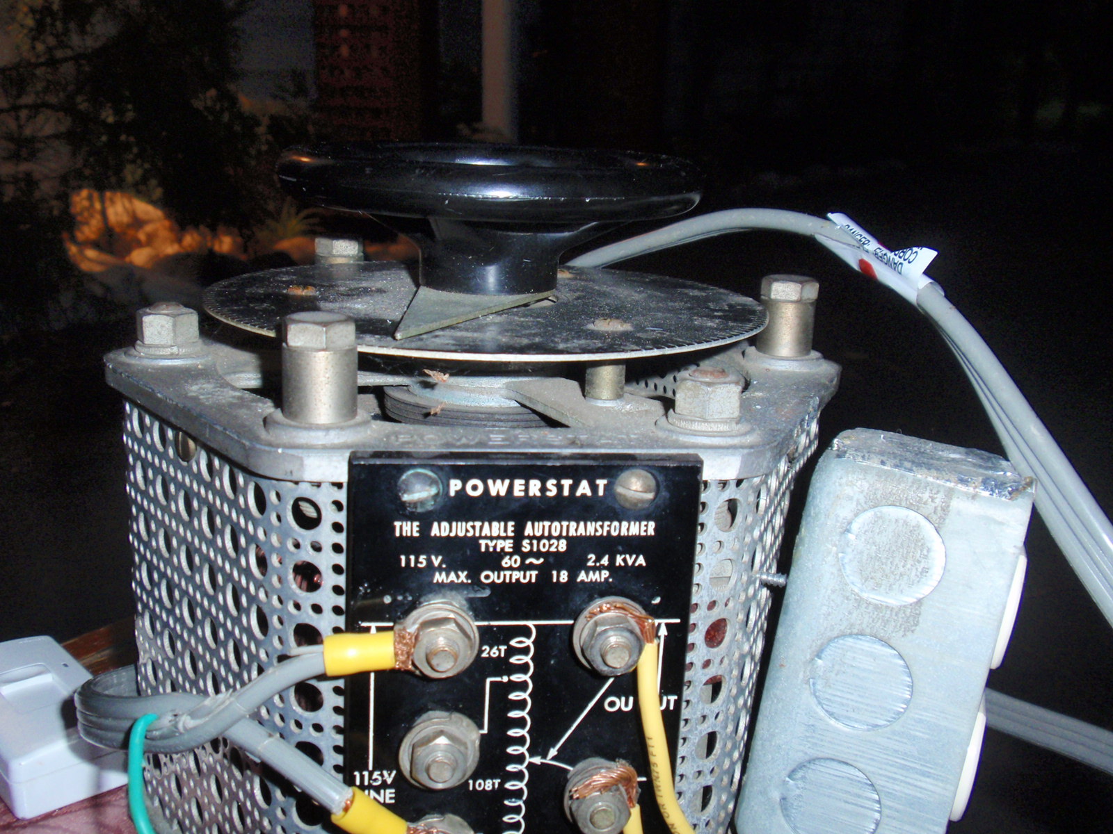
Power controlled with a variable autotransformer (for low power runs), up to 145V output with 120V input. This variac allows a maximum current of around 3 1/2 kVA before saturating.
The topload is two aluminum dryer ducts forming a double stacked toroid, each stack 8” by 2.5’. Primary coil is ~8 turns of 0.25” refrigerator tubing, secondary coil is 1100 turns of AWG 22 magnet wire on an 8” inner diameter concrete forming tube coated in polyurethane. The inner turns of the primary gets noticeably warm during operation, not suprising with an estimated 18.9 kA instantaneous current during capacitor discharge.
Low-res videos of the coil above
Very large topload test
A rubber inner tube was inflated and covered in aluminum tape to make a very large toroidal topload (5’ diameter). This method is not recommended without the use of a forming substance (paper miche or plaster etc) covering the tube because the high voltage arcs will puncture the rubber even when protected via metal tape. This is the last generation of the coil above, as the secondary base experienced severe flashovers during >4 kVa runs resulting in vaporization of parts of the lower windings. > 7’ arcs!
Early generation coil
This coil was based on a secondary coil wound on a 4” diameter PVC with 1300 turns of AWG 26 magnet wire. A ~2.5 kVA input from the microwave oven transformers in oil (see above) was used (an air core inductive current limiter was used to reduce current) along with smaller dryer duct toroids, smaller primary capacitor (~ 50 nF) make from WIMA MKP-10 pulse capacitors These are by design not as durable as FKP-1 but are a good deal cheaper and easier to find. I did experience a defective batch of these that could not tolerate the >400 discharges per second necessary, but nearly all others I have obtained have performed very well.
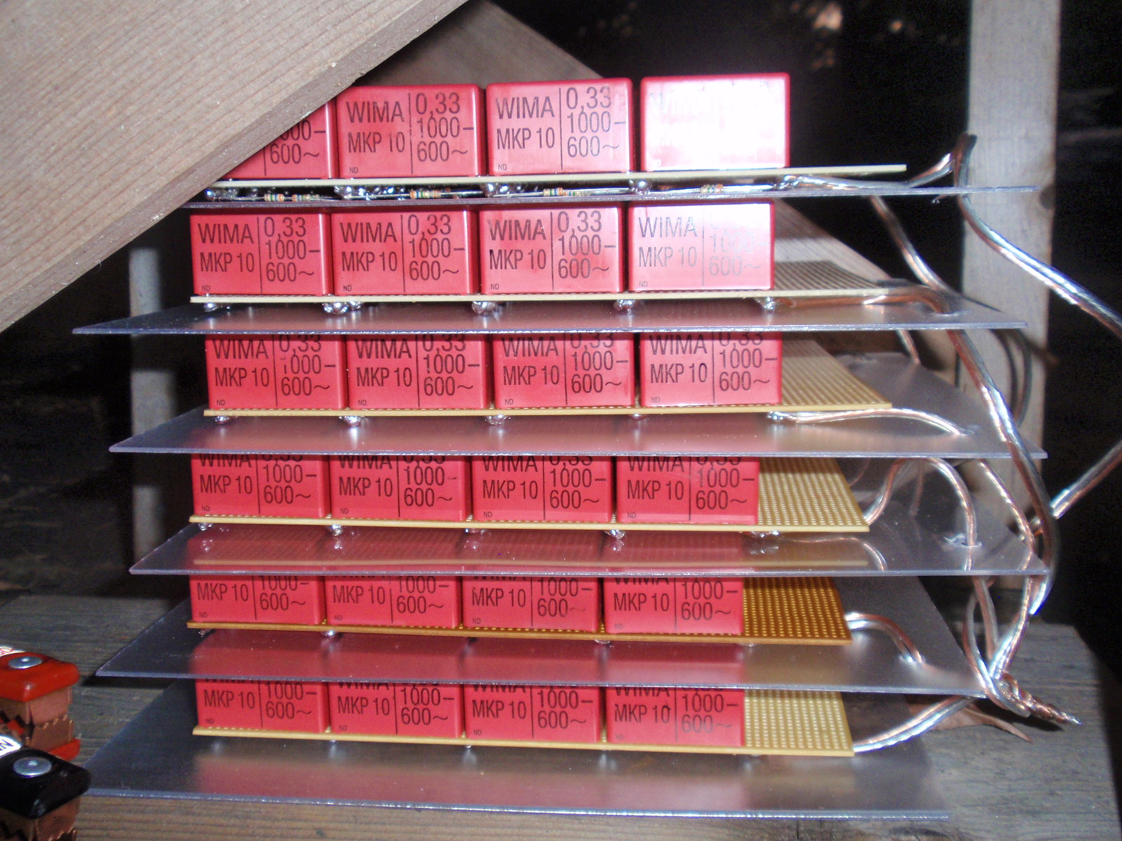
Note the bleed resistors at the top: I have not found these to be necessary for new capacitors (ie with no dielectric memory) that are then employed for tesla coils. Both the WIMA FKP-1 and MKP-10 mmcs mentioned on this page have not acquired any appreciable dielectric memory even after hours of total run time. Nevertheless, it is generally a good idea to include some form of current dissipation for large capacitors like these, as the energy they can release in a small amount of time is considerable.
The primary and secondary coil setup on wood supports, with an angle grinder-based ASRG in the ground to the right and the capacitor bank underneath the primary.
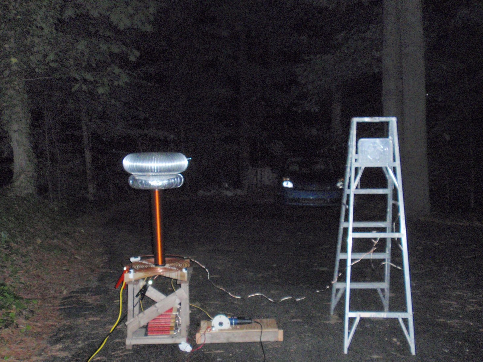
The jumper cables are attached to the strike rail protecting the primary coil and the secondary coil base, and lead to an 8’ copper grounding rod.